Texitile light ageing test instrument
CN1588059APatent Information
- Authority / Receiving Office
- CN · China
- Patent Type
- Applications(China)
- Current Assignee / Owner
- DONGHUA UNIV
- Filing Date
- 2004-09-23
- Publication Date
- 2005-03-02
- Estimated Expiration
- Not applicable · inactive patent
AI Technical Summary
Existing technology cannot conduct photoaging experiments in differentiated bands of visible light, and lacks narrow-band light sources for short-wavelength visible light bands, making it difficult to study the effects of illumination on textiles in different visible light bands.
The existing narrow-band filter is used as a light source, combined with an incandescent lamp to generate narrow-band visible light. The visible light sub-band photoaging experiment is carried out through the light-transmitting hole and sample slot in the experimental cavity. The experimental cavity uses thermal insulation materials and white reflective layers. Designed with electric fans for heat dissipation and ventilation.
It realizes photoaging experiments in different wavelength bands of visible light and solves the problem of lack of narrow-band light sources. The experimental instrument is compact, flexible and low-cost, and is suitable for photoaging experiments on textiles and other materials.
Smart Images
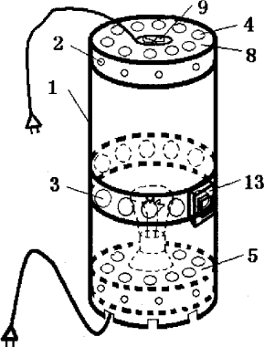
Figure 1.1
Abstract
Description
technical field
[0001] The invention relates to a performance testing instrument for textiles, in particular to a textile photoaging tester. Background technique
[0002] At present, the photoaging experiments of textiles are mainly carried out by ultraviolet photoaging experiments, and the photoaging experiments in the visible light band are full-band aging experiments. The narrow-band light source required for sub-band photoaging experiments is also difficult to buy. The commonly used lasers are mainly concentrated in the red and infrared bands. In the short-wavelength visible light band, there is no laser light source that can be used for photoaging. Therefore, it is currently impossible to carry out photoaging experiments with different bands of visible light. The academic community is still unclear about the impact of different bands of visible light on textiles. There is an urgent need for instruments for narrow-band aging experiments in this band to study the effects of different bands of visible light on textiles. The influence of light in various bands on textiles. Contents of the invention
[0003] The technical problem to be solved by the present invention is to provide a textile light aging tester, that is, to use the existing narrow-band filter used in optical analysis instruments as a light source for generating narrow-band visible light, and to use it for distinguishing bands of visible light. Photoaging experiments meet the needs of production and experiments.
[0004] In order to solve the above-mentioned technical problems, the technical solution adopted by the present invention is: a textile photoaging tester, comprising a test chamber 1 , a lower chassis 5 and an upper cover 8 . The lower chassis 5 and the upper cover plate 8 are respectively fixed on the bottom and the top of the experimental chamber 1, and can be installed through the mounting holes 2 with screws, or can be bonded or installed in a notch, and a bulb 6 is fixed in the middle of the lower chassis 5. The lamp holder 7 is provided with a light-transmitting hole 3 at the same height as the side wall of the experimental cavity 1, and a visible light narrow-band filter is arranged in the light-transmitting hole 3, and a sample tank 13 is installed outside the light-transmitting hole 3.
[0005] There can be one or more light-transmitting holes 3 distributed uniformly or unevenly, and the central axis of each light-transmitting hole 3 is aligned with the filament of the light bulb 6 .
[0006] A thermal insulation layer 10 and a sample bag 12 are arranged in the sample tank 13, and the thermal insulation layer 10 is outside the light transmission hole 3, and an identical circular hole is also opened at the position of the light transmission hole 3, and the sample bag 12 and the thermal insulation layer 10 The contact surface is directly facing the light transmission hole 3, and a similar circular hole is opened, and the other side of the sample bag 12 is not opened, and the opening 11 of the sample bag can face upward or horizontally.
[0007] The experimental chamber 1, the lower chassis 5, and the upper cover 8 are all heat-insulating, heat-resistant and opaque materials, and their inner surfaces are all coated with a white reflective layer. The lower part of the experimental chamber 1 touches the ground, the lower chassis 5, and the upper cover One or more ventilation openings 4 are arranged on the plate 8, and the number of ventilation openings 4 can be one or more evenly or unevenly distributed.
[0008] An electric fan 9 can also be installed on the upper cover plate 8 for exhaust heat dissipation.
[0009] The advantages of the present invention are:
[0010] 1. Utilize the existing visible light narrow-band filter used in other aspects to generate narrow-band visible light as a light source for sub-band photoaging experiments. Solved the problem that there is no experimental light source with narrow band in the visible light region.
[0011] 2. Utilize the continuous spectrum generated by incandescent lamps, and use narrow-band filters to take out any narrow-band visible light required for the experiment, so that visible light sub-band aging experiments for textiles and other materials can be carried out.
[0012] 3. The experimental instrument is compact in structure, easy to assemble and disassemble, flexible to use, and low in cost. Description of drawings:
[0013] figure 1 : Schematic diagram of the experimental chamber
[0014] figure 2 : Schematic diagram of lower chassis
[0015] image 3 : Schematic diagram of the upper cover
[0016] Figure 4 : Schematic diagram of the sample tank
[0017] Figure 5 : Schematic diagram of the experimental apparatus
[0018] Among them, the experimental chamber 1, the installation hole 2, the light hole 3, the vent 4, the lower chassis 5, the light bulb 6, the lamp holder 7, the upper cover plate 8, the electric fan 9, the heat insulation layer 10, the sample bag opening 11, the sample bag 12, sample well 13 detailed description
[0019] The present invention will be described in detail below in conjunction with the accompanying drawings.
[0020] combine Figure 1 to Figure 5 , The main inventive structure of the visible light sub-band textile light aging tester has four parts: the experimental chamber 1, the lower chassis 5, the upper cover plate 8 and the sample tank 13.
[0021] The main structure of the visible light sub-band textile light aging tester is made of heat-insulating wood. The experimental cavity is a drum with an inner diameter of 20cm, a thickness of 1cm, and a height of 40cm. The waist is 14cm away from the lower end. Twelve holes 3 with a diameter of 14 mm are drilled at a distance, and six to eight mounting holes are respectively opened on the lower part and the top of the drum. The central axis of each light transmission hole 3 is all aligned with the filament of the incandescent lamp 6 mounted on the lower chassis 5 . Visible light narrow-band filters are respectively installed in the twelve light-transmitting holes 3 . Twelve air vents 4 are opened at the lower end of this drum where the ground touches the ground. The lower chassis 5 is a disc with a diameter of 20cm, and a lamp holder 7 is installed in the center of the disc. There are dozens of small holes with a diameter of 5mm on the outer disc of the lamp holder 7 as ventilation holes, and six to eight installation holes are opened around the disc. . The wires of the incandescent lamp holder are drawn out from below, and a 100W incandescent lamp is mounted on the lamp holder.
[0022] Upper cover plate 8 is the disk of diameter 20cm, and a diameter is opened in the middle of the disk and is that the circular hole of 10cm is used for installing electric fan 9, and electric fan power cord is drawn from above. There are dozens of ventilation holes with a diameter of 5mm on the outer disc, and six to eight installation holes are opened around the disc. The lower chassis and the upper cover are respectively installed under and above the experimental chamber with screws, and can also be glued or made into slots for installation.
[0023] Twelve sample tanks 13 are respectively installed on the outside of the twelve light-transmitting holes 3 facing the light-transmitting holes. In the sample tanks 13, a heat insulating layer 10 and a sample bag 12 are arranged. The position of the light-transmitting hole 3 is also opened with an identical round hole, and the contact surface of the sample bag 12 and the heat insulation layer 10 is facing the light-transmitting hole 3, and an identical round hole is opened, and the other side of the sample bag 12 is not perforated.
[0024] This instrument can also be made of other materials that are heat-insulating, heat-resistant, and opaque. This instrument can also be used for photoaging experiments on paper, painting pigments, and textile dyes. It can also be used for other narrow-band visible light regions. related experiments.
Claims
Legal Information
Detailed Legal Status
Key Official Events
- 20101201 · 专利权的终止
- 20070502 · 授权
- 20050504 · 实质审查的生效
- 20050302 · 公开
Event Tags
Synapse Drug-Related Information
Drug-related linkage will appear here when reliable Synapse mapping is available.
Citation Information
Cited By
CN101498672B
CN104730226A
EXA
CN104730226B
EXA